Rebuilding winch control circuits: interference and contact arcing
Breaking an inductive circuit drives the load's stored energy into the opening contact gap. The arc that follows erodes the contacts and radiates interference into whatever shares the harness, which is why a burnt contactor and an unreliable instrument reading are usually the same fault.
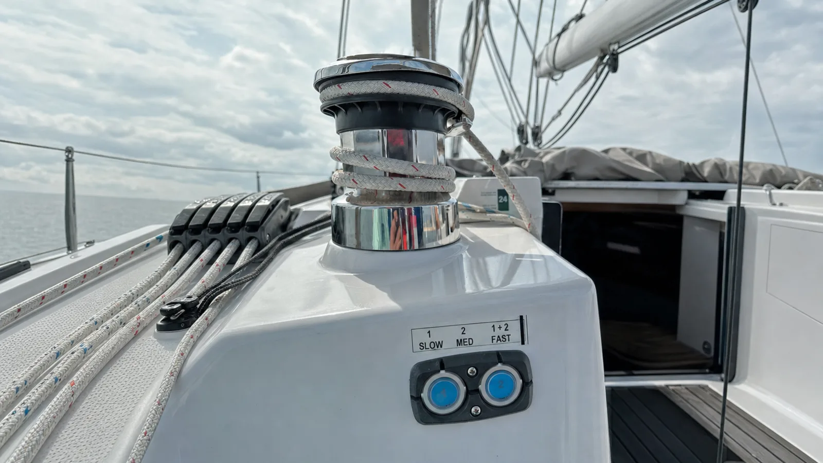
Current does not fall to zero the instant a contact opens. Breaking an inductive circuit — a winch contactor coil, a solenoid valve, a brake release — drives the load’s stored energy into the opening gap, and the resulting arc both erodes the contact and radiates interference into everything routed alongside it. The two failures arrive together, which is why replacing a burnt contactor on its own usually buys one season.
The problem is the same on an electric sheet winch at the coaming as on a mooring winch on a commercial deck. Only the currents and the duty cycle differ.
The arc is the load’s stored energy leaving through the contacts
An inductive load resists a change in current. When the contacts part, the collapsing field maintains current across a widening gap, sustaining an arc until the gap is long enough to extinguish it. The energy dissipated there leaves the contact faces as vaporised metal and is redeposited unevenly — the pitting and material transfer found on any set that has been switching unsuppressed.
The same event is a broadband interference source, coupling two ways: conducted, onto supply and return conductors shared with other equipment, and radiated, through the loop enclosed by the outgoing and returning conductors. Loop area and parallel run length decide how much of the second mechanism reaches its neighbours, which is why a circuit that worked for years starts misbehaving after a refit that changed nothing electrically.
The symptoms recur across vessels:
- intermittent response, most often on direction changes and at the stop-to-hoist transition
- resets or false readings on electronics sharing the same DC reference
- pitting on the contact faces, discolouration at terminals, blackened board pads around the driver
- behaviour that changes when a handheld radio is keyed nearby
Yacht winch control has its own failure pattern
An electric sheet or halyard winch is commanded from small, exposed controls — coaming rocker switches, deck footswitches, sometimes a handheld — that switch a contactor pack sited elsewhere, often in a locker some distance away. Three things follow from that arrangement.
The command run is long and thin relative to the motor feed, so it is the circuit most exposed to coupling from the feed it parallels. The switches themselves sit in salt water and are the most common source of a false or intermittent command, which is worth eliminating before any conclusion is drawn about the contactor. And because the winch reverses, the pack contains two contactors interlocked against each other; an interlock that has been defeated by a welded contact is the failure that matters most, since it puts both directions across the supply at once.
Contact welding rather than gradual erosion is the characteristic end state on a reversing pack, because the inrush of a stalled or heavily loaded motor is drawn through contacts that may still be bouncing. A winch that runs when commanded but will not stop is that fault, and it is not fixed by a new switch.
Suppression is selected for the switching type, not fitted generically
Two different problems are being solved, and the wrong component solves neither.
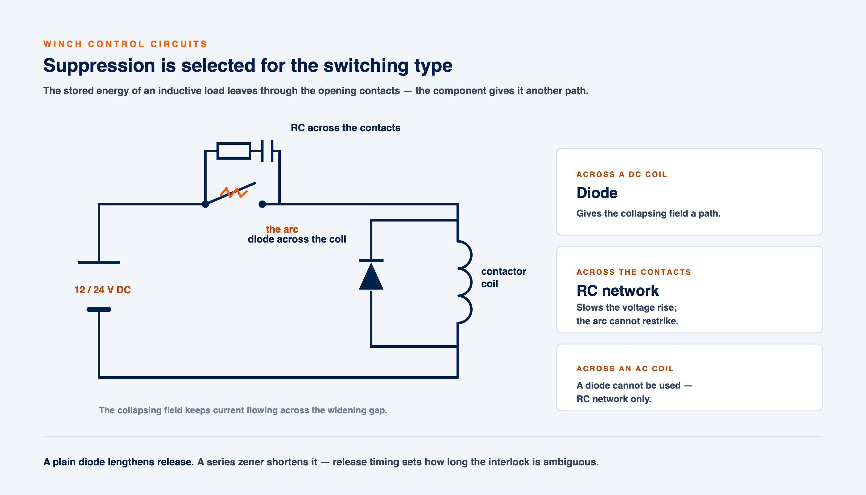
| Fitted | Switching | Network | What it does |
|---|---|---|---|
| Across a DC coil | DC | Diode, or diode with series zener | Gives the collapsing field a path so it does not appear across the contacts |
| Across contacts | AC or DC | RC network | Slows the rate of rise of voltage across the opening gap so the arc does not restrike |
| Across an AC coil | AC | RC network | A diode cannot be used; the RC limits the transient instead |
A plain diode across a DC coil is the cheapest fix and carries a cost worth knowing: it extends drop-out time, because current circulates until the winding resistance dissipates it. On a contactor holding a load, slower release means the main contacts part more slowly, lengthening the arc they draw. A zener in series with the diode raises the clamp voltage and shortens release, trading a higher transient for faster, cleaner separation. On a reversing winch pack, where release timing sets how long the interlock is ambiguous, that trade is the entire point.
An RC network across the contacts is sized against the load rather than chosen from a drawer. Fitted without regard to the circuit, it either fails to slow the recovery voltage or passes enough current at rest to hold a sensitive load partly energised. Leakage through the network and its temperature in service are both checked after fitting.
Arcing usually has a cause upstream of the contacts
Contact damage is a symptom. Before a set is replaced, the conditions that shortened its life are measured, because a new set fitted into unchanged conditions degrades on the same schedule:
- Coil voltage under command. Measured at the coil while the circuit is operating, not at rest. A coil below its rated voltage pulls in slowly and the contacts bounce, so one command becomes several make-and-break events.
- Voltage drop around the control loop. Excess drop destabilises operation and lengthens the interruption — and on yacht deck gear the control run is usually the longest thin conductor on the vessel.
- Terminal condition and torque. Loose screws, oxidised lugs and heat discolouration are recorded, and terminations torqued to the specified figure with a calibrated tool.
- Routing of the load wiring. Long runs parallel to motor and brake feeds raise coupling and change what the contacts see at the moment of interruption.
- Existing suppression. Frequently present, frequently wrong — a network intended for one switching type carried over to another, or a component cracked and no longer doing anything.
Wiring geometry does the work suppression cannot
Suppression reduces the source. Layout decides how much of what remains reaches anything else, and no snubber compensates for a control harness cable-tied to a motor feed for six metres.
- control wiring is separated from motor and brake feeds; where separation is impossible, distance is increased and parallel run length shortened
- outgoing and return conductors are kept together to hold the enclosed loop area down
- where screened cable is used, screens are terminated to the reference point the installation’s design intends, rather than left floating at one end
- control returns and electronics references are landed at planned points, not carried through thin splices made during an earlier repair
The rebuild is recorded so the next attendance starts from data
Deck gear faults are intermittent by nature, and an intermittent fault is only tractable against a baseline. As-found condition is recorded before anything is disturbed — contactor and relay types, coil ratings, terminal condition, wiring identifiers — and as-left readings recorded against them: insulation resistance per circuit, voltage drop under command, coil voltage at operation, and the torque applied at each termination.
That record is what makes the work auditable at survey, and what separates slow degradation from a new fault the following season. ISO 13297 and ABYC E-11 are cited for AC and DC wiring and connection discipline respectively, and nothing is claimed for them beyond what those documents cover.
Vessels in the northern Adriatic run a compressed season and lie unused through the winter, so control circuits sit in damp air for months and then go to daily cycling within weeks. Contact sets that were marginal at lay-up fail early in the first period of real use, which puts this work before the season rather than during it.
Control-gear rebuilds of this kind sit alongside passarelle and gangway control work on yachts and the deck machinery scope on commercial marine and shipping vessels. This work is carried out at the berth across Istria and the Gulf of Trieste.