Thermal imaging diagnostics: locating loose switchboard connections under load
Contact resistance at a termination is only visible as heat while current is flowing. A board surveyed at dockside idle will pass a joint that is already failing, which makes the stated load condition — not the camera — the part of a thermal survey that decides whether the result means anything.
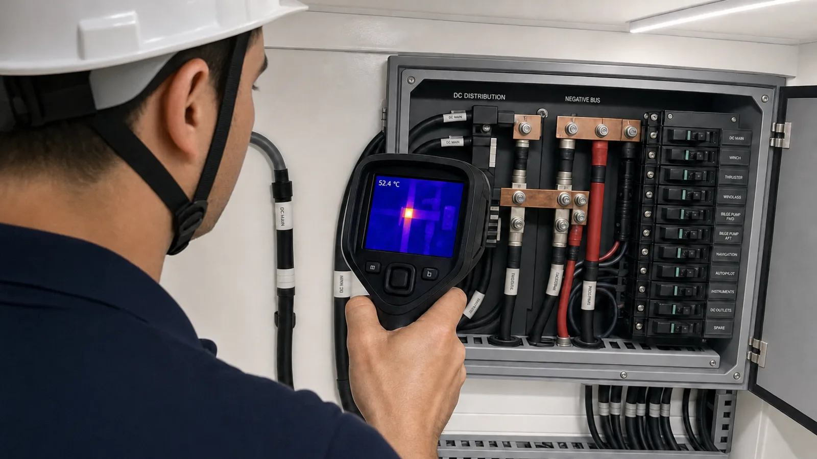
A distribution board scanned cold shows nothing useful. Contact resistance at a termination only declares itself as heat when current is flowing, which makes the load condition — not the camera — the part of a thermal survey that decides whether the result means anything.
Heat at a joint scales with the square of the current
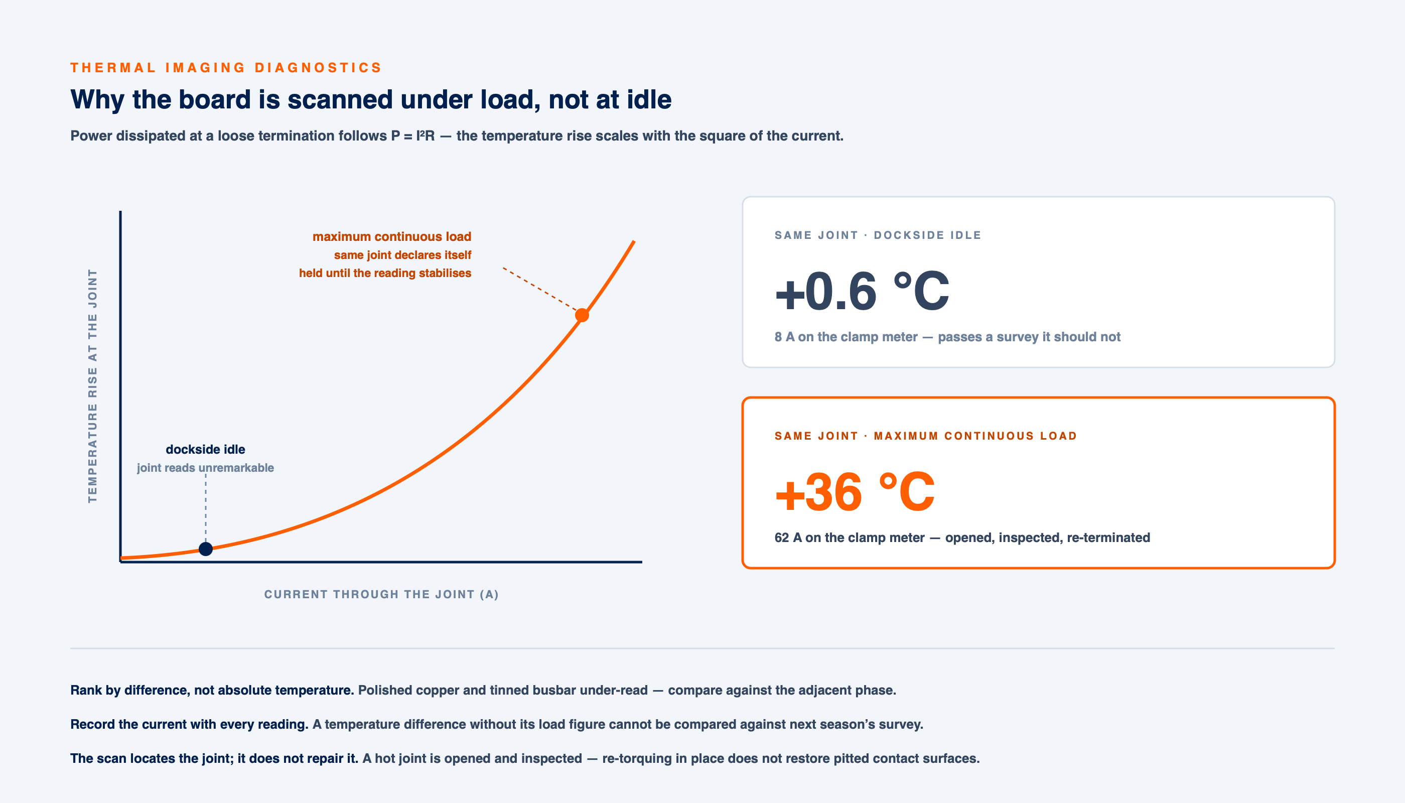
A loose, corroded or under-torqued termination is a rise in contact resistance. Power dissipated at that joint follows P = I²R, so the temperature rise scales with the square of the current passing through it. A joint that reads unremarkable at a few amps runs measurably hot at full load.
That square relationship is the reason a board is surveyed at the maximum continuous load the vessel’s operating pattern allows, and held there long enough for the temperature to stabilise. A scan taken at dockside idle, with the shore lead supplying a battery charger and little else, will pass a joint that is already failing.
On yacht and small commercial boards the recurring locations are consistent:
- busbar-to-cable lugs and stack-mounted links
- main switch terminals, both moving contacts and stationary blades
- fuse block connections and high-current fuse holders
- battery terminals, interconnects and DC distribution blocks on high-current runs
Assessment is by temperature difference, not absolute temperature
Two joints can sit at the same absolute temperature and be in entirely different condition, because surface finish, local airflow and mounting geometry all affect what the instrument reads. The usable measurement is the difference between a suspect joint and a reference: the same joint on an adjacent phase, an identically loaded circuit, or the surrounding ambient surfaces.
Published severity bands exist for electrical thermography, but they are written for shore installations and assume comparable loading, comparable mounting and a known reference. On a vessel those assumptions frequently do not hold — three phases are rarely loaded alike, and a board in an engine space sits in an airflow nothing ashore reproduces. Rather than apply a threshold that has not been shown to transfer, a suspect joint is ranked against its own comparison points and confirmed by opening it.
The load figure is recorded with every reading. A temperature difference without the current that produced it cannot be compared against next season’s survey of the same joint, because the dissipation term has changed underneath it.
Low-emissivity surfaces read cold when they are hot
The common way a survey produces a false negative is emissivity error. Bare polished copper and tinned busbar emit poorly in the infrared and reflect well, so an instrument set for a painted surface reports a hot joint as cool. The reflection of a warmer object elsewhere in the compartment can do the same in reverse.
The conditions that corrupt a reading are known and are handled at the time of measurement rather than argued about afterwards:
| Condition | Effect on the reading | Handling |
|---|---|---|
| Polished copper, tinned busbar | True temperature under-read | Compare against adjacent phase rather than trusting the absolute figure |
| Reflected apparent temperature | Cool surfaces read warm | Change viewing angle and re-measure |
| Cover removed | Airflow changes, joint cools | Record whether the cover was open or an inspection window was used |
| Load held too briefly | Gradient has not stabilised, rise under-read | Hold the load until the reading settles |
| Spot straddling metal and insulation | Mixed effective emissivity | Reduce distance or narrow the spot |
Where surface condition makes an absolute figure unreliable and no correction is possible, the survey leans entirely on difference measurements and mechanical verification.
The scan locates the joint; it does not repair it
A thermal survey narrows a fault to a termination. The corrective work is separate, and is carried out with the circuit isolated:
- the termination is opened and contact surfaces inspected for pitting, discolouration and oxidation
- the conductor is checked for damage, and strands annealed by heat are inspected for brittleness
- degraded lugs, blades and conductor tails are replaced rather than reused
- insulation adjacent to the joint is inspected, since it has been heated along with the conductor
- the connection is reassembled and torqued to the manufacturer’s figure with a calibrated tool
Re-torquing on its own does not necessarily restore a joint that has already run hot. Once contact surfaces have been through repeated heating, the pitting and oxide layer that raised the resistance remain after the fastener is tightened, and the joint returns. This is the reason a hot joint is opened and inspected rather than simply nipped up in place.
DC terminations carry the same problem at lower voltage
The dissipation relationship is indifferent to system voltage, and on 12 and 24 V DC installations the currents are high enough that the same joint fault produces more heat, not less. Main switches, busbars, fuse blocks, shunts and battery terminals are surveyed under the maximum continuous charge and discharge the installation sees, which on most vessels means with the engine running or the charger at full output rather than at rest.
Battery interconnects on AGM and flooded lead-acid banks are worth particular attention, because they combine high current with a corrosive local environment and are frequently disturbed during seasonal work.
Comparability across seasons is what catches slow degradation
A termination rarely fails between one week and the next. It degrades across cycles, and the signature is a temperature difference that grows year on year while the absolute figure stays within anything a technician would call normal. Catching that requires the surveys to be comparable, so each scan is logged with:
- board identification and the position of each joint measured
- system voltage and the current in amperes at the time of the scan
- which systems were running to produce that load
- ambient reference and whether covers were open
- the measured temperature differences against their reference points
Vessels in the northern Adriatic lie on the hard through the winter and return to a compressed season, so terminations sit unloaded through months of humidity and then go to sustained high load within weeks. Faults that were latent at lay-up appear during the first period of real running, which is what puts the survey before the season rather than during it.
Thermal survey work forms part of DC systems and charging and of board inspection on shore power and 230 V AC installations. This work is carried out at the berth across Istria and the Gulf of Trieste.